redsocks升级记录

一直在用redsocks做流量转发,用着还是挺不错的,但是偶尔还是会hang住,导致网络卡住。老早就有升级的想法,一直没有动手。

什么是redsocks?

This tool allows you to redirect any TCP connection to SOCKS or HTTPS proxy using your firewall, so redirection may be system-wide or network-wide.

When is redsocks useful?

  • you want to route part of TCP traffic via OpenSSH DynamicForward Socks5 port using firewall policies. That was original redsocks development goal;
  • you use DVB ISP and this ISP provides internet connectivity with some special daemon that may be also called “Internet accelerator” and the accelerator acts as a proxy and has no “transparent proxy” feature and you need it. Globax was an example of alike accelerator, but Globax 5 has transparent proxy feature. That was the second redsocks` development goal;
  • you have to pass traffic through proxy due to corporate network limitation. That was never a goal for redsocks, but users have reported success with some proxy configurations.

以上是官方介绍。功能确实很强大,毕竟是俄国大佬的作品,继承了俄国产品强大而又粗糙的刻板印象。翻了他的repo,发现最后更新是2019年,而且还是改typo,其他的issue没有回复,大概大佬也不打算维护了吧。找了好久替代,发现了它的一个fork,似乎改了不少东西,就拖下来试试看吧。运行了一晚上,稳定性似乎还不错。

github地址 https://github.com/semigodking/redsocks

该repo依赖openssl和libevent2,libevent2在树莓派的repo中没有了,所以只能现编译。

现在把安装过程记录一下(仅限Raspberry Pi):

#安装openssl开发包

sudo apt install libssl-dev

#获取代码

wget https://github.com/libevent/libevent/releases/download/release-2.1.12-stable/libevent-2.1.12-stable.tar.gz

tar xvfz libevent-2.1.12-stable.tar.gz

cd libevent-2.1.12-stable

编译、安装

make
sudo make install

#克隆redsocks2的代码

git clone https://github.com/semigodking/redsocks

cd redsocks

make DISABLE_SHADOWSOCKS=1 ENABLE_STATIC=1

编译完,修改之前redsocks的配置文件、替换redsocks文件,重启服务即可。

目前暂时稳定。

树莓派充当airplay接收器

iOS升级以后,新版本经常不兼容xbian之类自带的airplay功能,目前来Shairport的支持还是不错的。我在新的树梅派3b+上编译了一下,支持ios 11.0.4版本。

首先升级树莓派

sudo apt-get update
sudo apt-get upgrade

然后安装依赖包

sudo apt-get install autoconf automake avahi-daemon build-essential git libasound2-dev libavahi-client-dev libconfig-dev libdaemon-dev libpopt-dev libssl-dev libtool xmltoman

下载shairport源码

git clone https://github.com/mikebrady/shairport-sync.git

生成配置文件

cd shairport-sync
autoreconf -i -f
./configure --with-alsa --with-avahi --with-ssl=openssl --with-systemd --with-metadata

编译安装

make
sudo make install

设置为自动启动

sudo systemctl enable shairport-sync

启动

sudo service shairport-sync start

然后就可以在手机里面找到airplay设备,raspberrypi了。

Auto start a java Swing GUI program when raspberry boots

I planed make an self-desgin photo or movie player base on Raspberry. Also I can use it as photo frame. If I need improve the performance of the PI, I need write it with Python, I think.


Part 1 – Build the Foundation

In this part, we will focus on preparing Raspbian Lite.

1. Download the latest Raspbian Lite image.
2. Format the SD / microSD card with Raspbian Lite (Plenty of guides out there on how to do this. For macOS, Linux, and Windows users, Etcher is an easy to use application that can help you do this.)
3. Insert the SD / microSD card into the Pi.
4. Connect the Pi to the Internet using an Ethernet cable. If you want to use Wi-Fi instead, you will have to read on how to configure your wireless receiver using the command line after your Pi has finished booting.
5. Connect your TV / Monitor and keyboard. (Mouse is optional at this time.) Turn on the Pi. The Pi should boot up successfully and a prompt to log in will appear.
6. Log into Raspbian. The username is pi and the password is raspberry.


7. We will install Xorg. To do this type in:

sudo apt-get install –no-install-recommends xserver-xorg

sudo apt-get install –no-install-recommends xinit

now, you can write you java program now. For example, I wrote a test program with a button in the center of screen. once I click the button, the window will change to the full size of the screen.

import java.awt.FlowLayout;
import java.awt.event.ActionEvent;
import java.awt.event.ActionListener;

import javax.swing.JButton;
import javax.swing.JFrame;

public class FullScreenTest {
public static void main(String[] args) {
final JFrame f = new JFrame(“FullScreenTest”);
final JButton btn = new JButton(“FullScreen”);
btn.addActionListener(new ActionListener() {
public void actionPerformed(ActionEvent e) {
if (btn.getText().equals(“FullScreen”)) {
f.dispose();
f.setUndecorated(true);
f.getGraphicsConfiguration().getDevice().setFullScreenWindow(f);
f.setVisible(true);
btn.setText(“NormalMode”);
} else {
f.dispose();
f.setUndecorated(false);
f.getGraphicsConfiguration().getDevice().setFullScreenWindow(null);
f.setVisible(true);
btn.setText(“FullScreen”);
}
}
});

f.getContentPane().setLayout(new FlowLayout());
f.getContentPane().add(btn);
f.pack();
f.setLocationRelativeTo(null);
f.setDefaultCloseOperation(JFrame.EXIT_ON_CLOSE);
f.setVisible(true);
}
}


Pack the file into a jar file like GUI.jar.

In order to have a command or program run when the Pi boots, you can add commands to the rc.local file. This is especially useful if you want to be able to plug your Pi in to power headless, and have it run a program without configuration or a manual start.

EDITING RC.LOCAL

On your Pi, edit the file /etc/rc.local using the editor of your choice. You must edit with root, for example:

sudo nano /etc/rc.local

Add commands below the comment, but leave the line exit 0 at the end, then save the file and exit.

sudo xinit /usr/local/jdk1.8.0_77/bin/java -jar /usr/local/mypi/GUI.jar — :1 &


Reboot your PI, then done!

MOUNT AN SMB NETWORK DRIVE ON RASPBERRY PI

original post: http://geeks.noeit.com/mount-an-smb-network-drive-on-raspberry-pi/

In this tutorial we will describe how to connect your Raspberry Pi to a network drive and permanently mount it to your system. Even though this article uses a Raspberry Pi as an example to connect to an SMB drive, the steps used can be applied to any Debian based system, such as Ubuntu.

If you have a Raspberry Pi you might have noticed that the storage possibilities are kind of limited unless you have some external storage. Even though you can get SD cards with 64+gb of storage, you probably want more if you have a lot of music and movies that you are streaming through your Pi.

There are several choices when it comes to storage for your Pi, such as network drives, flash drives, or external USB HDDs. Using a network drive you can not only access your files from the Pi, but from any computer connected to your network, which is very convenient.

Prerequisites

Before we start, I will assume you already

  1. have a network drive connected to your LAN, and
  2. know its LAN IP address

Note: remember to change all text in red to your own values.


Installation

In order to mount the drive, you need to have cifs-utils installed on your system. If you are running a newer version of Raspbian or RaspBMC you should already have this installed. You can check whether it is installed or not by running the following command:

dpkg -s cifs-utils

If it is installed, it should output something like this:

Package: cifs-utils
 Status: install ok installed
 Priority: optional
 Section: otherosfs
 Installed-Size: 189
 Maintainer: Debian Samba Maintainers <pkg-samba-maint@lists.alioth.debian.org> Architecture: armhf
 Version: 2:5.5-1
 ...

If it says that it’s not installed, you need to install it:

sudo apt-get install cifs-utils


Mounting unprotected (guest) network folders

You might have public folders on your network drive that can be accessed by anyone without having to provide any credentials. These are mounted in the same way as password-protected folders (we will mount these in the next section), but with a few different options.

First, let’s create a directory on the Pi where we want to mount the directory. You will need a separate directory for each network folder that you want to mount. I will create the folders in the /media folder:

sudo mkdir -p /media/networkshare/public

Then edit your /etc/fstab file (with root privileges) and add this line:

//192.168.0.18/publicshare /media/networkshare/public cifs guest,uid=1000,gid=1000,iocharset=utf8 0 0

The first part is the IP of your network drive, and the public folder you want to mount.
The second part is the folder on your local machine where you want to mount the network share.
The third part indicates what type of drive you want to mount (cifs).

The last part is the set of options you can pass, and here’s an explanation of the ones we are using:

  • guest is basically telling the network drive that it’s a public share, and you don’t need a password to access it (not to confuse with username),
  • uid=1000 makes the Pi user with this id the owner of the mounted share, allowing them to rename files,
  • gid=1000 is the same as uid but for the user’s group,
  • iocharset=utf8 allows access to files with names in non-English languages.

Note: If there is any space in the server path, you need to replace it by \040, for example //192.168.0.18/My\040Documents

To find the uid and gid for your username, use the following command:

id username

Now that we have added this to our /etc/fstab, we need to (re)mount all entries listed in /etc/fstab:

sudo mount -a

Now you can access your network drive from /media/networkshare/public (or wherever you chose to mount it).


Mount password-protected network folders

Mounting a password-protected share is very similar to mounting a public ones, with some minor changes to the options we pass. Let’s start by making a new folder where we want to mount the password-protected share:

sudo mkdir -p /media/networkshare/protected

Again, open /etc/fstab (with root privileges), and add this line:

//192.168.0.18/protectedshare /media/networkshare/protected cifs username=msusername,password=mspassword,uid=1000,gid=1000,iocharset=utf8 0 0

While this is a perfectly valid way of mounting your protected folder, it’s not very secure. Since /etc/fstab is readable by everyone, so are your credentials in it. So, let’s make it more secure by using a credentials file. This file will contain nothing else but your username and password, but we will make readable only to you. This way, other users on the system won’t be able to see your credentials.

Using a text editor, create a file that will contain the credentials for your protected network share:

vim ~/.smbcredentials

Enter your username and password for the protected share in the file:

username=msusername
password=mspassword

Save the file.

Change the permissions of the file to make sure only you can read it:

chmod 600 ~/.smbcredentials

Then edit your /etc/fstab file and change the line where we are mounting the protected share to look like this:

//192.168.0.18/protectedhare /media/networkshare/protected cifs credentials=/home/username/.smbcredentials,uid=1000,gid=1000,iocharset=utf8 0 0

Save the file.

Again, we need to (re)mount all entries listed in /etc/fstab:

sudo mount -a


Now you’re all set to access your public and protected folders from your Pi.


How to wake up a pc by PHP

source: 
http://php.net/manual/en/ref.sockets.php
http://www.rkrishardy.com/2009/12/permission-denied-13-when-opening-socket-in-php-apache/

<?php
/**
 * Wake-on-LAN
 *
 * @return boolean
 *   TRUE:    Socked was created successfully and the message has been sent.
 *   FALSE:   Something went wrong
 *
 * @param string|array  $mac   You will WAKE-UP this WOL-enabled computer, you
 *                             need to add the MAC-address here. Mac can be
 *                             array too.
 *
 * @param string|array  $addr  You will send and broadcast to this address.
 *                             Normally you need to use the 255.255.255.255
 *                             address, so I made it as the default. You don't need to do anything with this.
 *                       
 *                             If you get permission denied errors when using
 *                             255.255.255.255 have permission denied problems
 *                             you can set $addr = false to get the broadcast
 *                             address from the network interface using the
 *                             ifconfig command.
 *
 *                             $addr can be array with broadcast IP values
 *
 * Example 1:
 *   When the message has been sent you will see the message "Done...."
 *   if ( wake_on_lan('00:00:00:00:00:00'))
 *      echo 'Done...';
 *   else
 *      echo 'Error while sending';
 */

function wake_on_lan($mac, $addr=false, $port=7) {
    if ($addr === false){
        exec("ifconfig | grep Bcast | cut -d \":\" -f 3 | cut -d \" \" -f 1",$addr);
        $addr=array_flip(array_flip($addr));
    }
    if(is_array($addr)){
        $last_ret = false;
        for ($i = 0; $i < count($addr); $i++)
            if ($addr[$i] !== false) {
                $last_ret = wake_on_lan($mac, $addr[$i], $port);
            }
        return $last_ret;
    }
    if (is_array($mac)){
        $ret = array();
        foreach($mac as $k =< $v)
            $ret[$k] = wake_on_lan($v, $addr, $port);
        return $ret;
    }
    //Check if it's an real MAC-address and split it into an array
    $mac = strtoupper($mac);
    if (!preg_match("/([A-F0-9]{1,2}[-:]){5}[A-F0-9]{1,2}/", $mac, $maccheck))
        return false;
    $addr_byte = preg_split("/[-:]/", $maccheck[0]);
 
    //Creating hardware adress
    $hw_addr = '';
    for ($a = 0; $a < 6; $a++)//Changing mac adres from HEXEDECIMAL to DECIMAL
        $hw_addr .= chr(hexdec($addr_byte[$a]));
  
    //Create package data
    $msg = str_repeat(chr(255),6);
    for ($a = 1; $a <= 16; $a++)
        $msg .= $hw_addr;
    //Sending data
    if (function_exists('socket_create')){
        //socket_create exists
        $sock = socket_create(AF_INET, SOCK_DGRAM, SOL_UDP);    //Can create the socket
        if ($sock){
            $sock_data = socket_set_option($sock, SOL_SOCKET, SO_BROADCAST, 1); //Set
            if ($sock_data){
                $sock_data = socket_sendto($sock, $msg, strlen($msg), 0, $addr,$port); //Send data
                if ($sock_data){
                    socket_close($sock); //Close socket
                    unset($sock);
                    return true;
                }
            }
        }
        @socket_close($sock);
        unset($sock);
    }
    $sock=fsockopen("udp://" . $addr, $port);
    if($sock){
        $ret=fwrite($sock,$msg);
        fclose($sock);
    }
    if($ret)
        return true;
    return false;  
}

if (@wake_on_lan('00:00:00:00:00:00')) {
    echo 'Done...';
} else {
    echo 'Error while sending';
}
?>

树莓派spi液晶屏支持(fbtft)[转]


转自 老徐拉灯 的博客

原文地址:http://blog.csdn.net/xdw1985829/article/details/39583239

树莓派官方支持av及HDMI输出,板子上预留了一个csi接口的液晶显示屏,但是一直没有相应的模组出现。在很多应用场合我们需要一些小型的液晶屏显示一些基本的信息,所以小屏驱动很是必要。

在github上有一个开源工程:notro/fbtft,完整的实现了framebuffer驱动,让树莓派完美支持tft液晶,下面对移植过程进行一个简单说明

一、官网地址

工程首页:https://github.com/notro

fbtft源码:https://github.com/notro/fbtft

编译好的固件(基于3.12.25+):https://github.com/notro/rpi-firmware

使用说明(wiki):https://github.com/notro/fbtft/wiki

二、使用编译好的固件(3.12.25+)

环境:树莓派

https://github.com/notro/rpi-firmware

1、打开SPI

树莓派默认spi是关掉的,我们需要打开

sudo vi /etc/modprobe.d/raspi-blacklist.conf

把下面这句话前面的#号删掉

blacklist spi-bcm2708

2、下载:

1)以模块的形式编译进内核(需要手动或脚本加载模块)3.12.25+(试验成功
sudo REPO_URI=https://github.com/notro/rpi-firmware rpi-update
2)直接编译进内核(笔者没有试验
sudo REPO_URI=https://github.com/notro/rpi-firmware BRANCH=builtin rpi-update

3)以模块的形式编译进内核(需要手动或脚本加载模块,最新版本,笔者试过启动不起来,不知道哪出问题

sudo REPO_URI=https://github.com/notro/rpi-firmware BRANCH=latest rpi-update

4)直接下载压缩包,手动安装(适合树莓派不能联网的时候

http://tronnes.org/downloads/2014-06-20-wheezy-raspbian-2014-07-25-fbtft-master-firmware.zip

3、配置

1)手动加载模块:

sudo modprobe fbtft_device name=adafruit22

name后面的名字,要跟相应的液晶驱动芯片移植

笔者使用的液晶芯片为:fb_ra8875,所以这里写的是:er_tftm050_2

其它芯片请查阅:https://github.com/notro/fbtft/blob/master/fbtft_device.c 文件

正常会提示以下信息

fbtft_device:  SPI devices registered:
fbtft_device:      spidev spi0.0 500kHz 8 bits mode=0x00
fbtft_device:      spidev spi0.1 500kHz 8 bits mode=0x00
fbtft_device:  ‘fb’ Platform devices registered:
fbtft_device:      bcm2708_fb id=-1 pdata? no
fbtft_device: Deleting spi0.0
fbtft_device:  GPIOS used by ‘adafruit22’:
fbtft_device:    ‘reset’ = GPIO25
fbtft_device:    ‘led’ = GPIO23
fbtft_device:  SPI devices registered:
fbtft_device:      spidev spi0.1 500kHz 8 bits mode=0x00
fbtft_device:      fb_hx8340bn spi0.0 32000kHz 8 bits mode=0x00

graphics fb1: fb_hx8340bn frame buffer, 176×220, 75 KiB video memory, 16 KiB buffer memory, fps=20, spi0.0 at 32 MHz

在/dev/目录下出现: /dev/fb1设备

2)自动加载模块

sudo vi  /etc/modules

加入以下语句,既可以在启动时自动加载模块

spi-bcm2708

fbtft_device name=er_tftm050_2  speed=28000000 fps=25 verbose=0

红色部分根据实际情况调整,可能出现花屏现象
4、使用(官方给出的方法,笔者测试不成功)

1)手动启动x11和控制台到新的液晶屏
X Windows显示在fb1上:
$FRAMEBUFFER=/dev/fb1 startx

Console显示在fb1上:
$con2fbmap 1 1

2)自动登陆x11

sudo vi /etc/inittab
#1:2345:respawn:/sbin/getty –noclear 38400 tty1
1:2345:respawn:/bin/login -f pi tty1 </dev/tty1 >/dev/tty1 2>&1

sudo vi /etc/rc.local

su -l pi -c “env FRAMEBUFFER=/dev/fb1 startx &”

5、使用(笔者使用这个测试通过)

1)将fb0上的内容直接拷贝到fb1上,fb0和fb1同步

https://github.com/notro/fbtft/wiki/Framebuffer-use#framebuffer-mirroring

$git clone https://github.com/tasanakorn/rpi-fbcp

$cd rpi-fbcp/
$mkdir build
$cd build/
$cmake ..
$make
$sudo install fbcp /usr/local/bin/fbcp

启动:fbcp &

关闭fbcp:killall fbcp

2)启动时使用fb1

$sudo apt-get install xserver-xorg-video-fbdev

$sudo vi /usr/share/X11/xorg.conf.d/99-fbdev.conf

加入以下语句:

Section “Device”
Identifier “myfb”
Driver “fbdev”
Option “fbdev” “/dev/fb1”
EndSection

启动:startx


测试:

apt-get -y install fbi

fbi -d /dev/fb1 -T 1 -noverbose -a test.jpg

三、由内核及源码编译

1、下载、编译内核源码:

请见《树莓派开发系列教程8——树莓派内核编译与固件升级

2、下载、编译fbtft源码

$cd linux(进入下载好的内核源码目录)

$cd drivers/video

$git clone https://github.com/notro/fbtft.git(下载fbtft源码,也可以在别的地方下载好,拷贝过来)

   修改内核源码的Kconfig及Makefine

  Add to drivers/video/Kconfig:   source “drivers/video/fbtft/Kconfig”

  Add to drivers/video/Makefile:  obj-y += fbtft/

$make menuconfig(在配置界面加入所选用液晶的驱动支持)

  1.  Device Drivers  —>
  2.  Graphics support  —>
  3. <M> Support for small TFT LCD display modules  —>
  4. <M>   FB driver for the HX8353D LCD Controller
  5. <M>   FB driver for the ILI9320 LCD Controller
  6. <M>   FB driver for the ILI9325 LCD Controller
  7. <M>   FB driver for the ILI9340 LCD Controller
  8. <M>   FB driver for the ILI9341 LCD Controller
  9. < >     FB driver for the ILI9481 LCD Controller
  10. <M>   FB driver for the ILI9486 LCD Controller
  11. <M>   FB driver for the PCD8544 LCD Controller
  12. <M>   FB driver for the RA8875 LCD Controller

$make

基于树莓派Raspberry: 字符设备内核驱动程序框架编写[转]

之前写了一篇移植2.4寸TFT驱动到树莓派的文章,那篇博文中的驱动代码是国外大牛写的,看了一下,还是有很多地方没理解,是得好好再学习一下内核驱动的编写,这里就从字符设备驱动开始,采用最简单的LED驱动来建立内核驱动移植的驱动框架.

个人原创,转载请注明原文出处:

http://blog.csdn.net/embbnux/article/details/17712547

参考文章:

http://blog.csdn.net/hcx25909/article/details/16860725

内核驱动与普通单片机模块驱动的差别就是在于,写内核驱动的时候,要提供内核调用的接口,使内核能找到相应的驱动入口,用户通过告诉内核要干嘛,内核再去调用那个驱动,驱动的最底层和单片机模块是一样的,同样是对GPIO的操作,配置输入输出,以及某些特殊的寄存器. LED的点亮就是对GPIO的操作 .

对于ARM的GPIO调用需要通过IO映射的方法,要操作内存上对应的地址.

对于bcm2708上的io对应关系,可以查看bcm2835的手册,和stm32基本上是一样的,因为同为ARM体系:SouthEast

我参考的那博客讲这个比较清楚,可以参考下,由于树莓派的内核以及很好的提供了GPIO调用的接口,即把内存操作封装了很好,这里就不像那篇博客那样再自己写函数通过内存操作来进行GPIO操作,觉得有点麻烦,但是对于学好底层很有用.

  一  首先上个驱动程序


这里直接把该程序添加到内核的源码目录里面,也可在自己的目录下,但是要写Makefile.

在/drivers/char/新建rasp_led.c,内核中的kconfig文件和makefile文件,参照前一篇文章

led.c:

1
2
3
4
5
6
7
8
9
10
11
12
13
14
15
16
17
18
19
20
21
22
23
24
25
26
27
28
29
30
31
32
33
34
35
36
37
38
39
40
41
42
43
44
45
46
47
48
49
50
51
52
53
54
55
56
57
58
59
60
61
62
63
64
65
66
67
68
69
70
71
72
73
74
75
76
77
78
79
80
81
82
83
84
85
86
87
88
89
90
91
92
93
94
95
96
97
98
99
100
101
102
103
104
105
106
107
108
109
110
111
112
113
114
115
116
117
118
119
120
121
122
123
124
125
/********************************************************************/
/***************Rasp led 驱动程序************************************/
/***************作者: Embbnux Ji*************************************/
/***************博客: http://blog.csdn.net/embbnux/ *****************/
/********************************************************************/
#include <linux/kernel.h>
#include <linux/module.h>
#include <linux/device.h>
#include <mach/platform.h>&nbsp;&nbsp;&nbsp;&nbsp;&nbsp;&nbsp;
#include <linux/platform_device.h>
#include <linux/types.h>
#include <linux/fs.h>
#include <linux/ioctl.h>
#include <linux/cdev.h>
#include <linux/delay.h>
#include <linux/uaccess.h>
#include <linux/init.h>
#include <linux/gpio.h>
#define DEVICE_NAME "Pi_Led"
#define DRIVER_NAME "pi_led"
//class声明内核模块驱动信息,是UDEV能够自动生成/dev下相应文件
static dev_t pi_led_devno; //设备号
static struct class *pi_led_class;
static struct cdev pi_led_class_dev;
struct gpio_chip *gpiochip;
#define led_pin 4 //gpio 4
//这部分函数为内核调用后open的设备IO操作,和裸板程序一样
int open_flag=0;
static int pi_led_open(struct inode *inode, struct file *filp)
{
 printk("Open led ing!\n");
 if(open_flag ==0){
 open_flag =1;
 printk("Open led success!\n");
 return 0;
 }
 else{
 printk("Led has opened!\n");
 }
 return 0;
}
//这部分函数为内核调用后ioctl的设备IO操作,和裸板程序一样
static long pi_led_ioctl(struct file *filp, unsigned int cmd, unsigned long arg)
{
 switch(cmd){
 case 0:
 gpiochip->set(gpiochip, led_pin, 0);
 printk("Led up!\n");
 break;
 case 1:
 gpiochip->set(gpiochip, led_pin, 1);
 printk("Led down!\n");
 break;
 }
 return 0;
}
static int pi_led_release(struct inode *inode,struct file *file){
 printk("Led has release!\n");
 return 0;
}
//file_operations使系统的open,ioctl等函数指针指向我们所写的led_open等函数,
//这样系统才能够调用
static struct file_operations pi_led_dev_fops = {
 .owner =THIS_MODULE,
 .open =pi_led_open,
 .unlocked_ioctl = pi_led_ioctl,
 .release = pi_led_release,
};
static int is_right_chip(struct gpio_chip *chip, void *data)
{
if (strcmp(data, chip->label) == 0)
 return 1;
 return 0;
}
//内核加载后的初始化函数.
static int __init pi_led_init(void)
{
 struct device *dev;
 int major; //自动分配主设备号
 major = alloc_chrdev_region(&pi_led_devno,0,1,DRIVER_NAME);
 //register_chrdev 注册字符设备使系统知道有LED这个模块在.
 cdev_init(&pi_led_class_dev, &pi_led_dev_fops);
 major = cdev_add(&pi_led_class_dev,pi_led_devno,1);
 //注册class
 pi_led_class = class_create(THIS_MODULE,DRIVER_NAME);
 dev = device_create(pi_led_class ,NULL,pi_led_devno,NULL,DRIVER_NAME);
 gpiochip = gpiochip_find("bcm2708_gpio", is_right_chip);
 gpiochip->direction_output(gpiochip, led_pin, 1);
 gpiochip->set(gpiochip, led_pin, 0);
 printk("pi led init ok!\n");
 return 0;
}
//内核卸载后的销毁函数.
void pi_led_exit(void)
{
 gpio_free(led_pin);
 device_destroy(pi_led_class,pi_led_devno);
 class_destroy(pi_led_class);
 cdev_del(&pi_led_class_dev);
 unregister_chrdev_region(pi_led_devno, 1);
 printk("pi led exit ok!\n");
}
module_init(pi_led_init);
module_exit(pi_led_exit);
MODULE_DESCRIPTION("Rasp Led Driver");
MODULE_AUTHOR("Embbnux Ji < http://blog.csdn.net/embbnux >");
MODULE_LICENSE("GPL");

二  源码框架分析

我们首先从内核模块的入口,module_init(pi_led_init)这个函数看起,可以看出初始化后调用pi_led_init这个函数.

1
2
3
4
5
6
7
8
9
10
11
12
13
14
15
16
17
18
19
20
21
//内核加载后的初始化函数.
static int __init pi_led_init(void)
{
 struct device *dev;
 int major; //自动分配主设备号
 major = alloc_chrdev_region(&pi_led_devno,0,1,DRIVER_NAME);
 //register_chrdev 注册字符设备使系统知道有LED这个模块在.
 cdev_init(&pi_led_class_dev, &pi_led_dev_fops);
 major = cdev_add(&pi_led_class_dev,pi_led_devno,1);
 //注册class
 pi_led_class = class_create(THIS_MODULE,DRIVER_NAME);
 dev = device_create(pi_led_class ,NULL,pi_led_devno,NULL,DRIVER_NAME);
 gpiochip = gpiochip_find("bcm2708_gpio", is_right_chip);
 gpiochip->direction_output(gpiochip, led_pin, 1);
 gpiochip->set(gpiochip, led_pin, 0);
 printk("pi led init ok!\n");
 return 0;
}

初始化时首先分配给这个函数设备号,注册该设备,通过class注册使能够在/dev/目录下自动生成相应的设备文件,用户通过操作这个文件,来告诉内核怎么做.

由于是字符设备,所以对该文件的操作通过open,write,ioctl等函数,所以要把这个函数和底层的操作函数对应起来,这就要用到file_operation这个结构体,来声明:

1
2
3
4
5
6
7
8
//file_operations使系统的open,ioctl等函数指针指向我们所写的led_open等函数,
//这样系统才能够调用
static struct file_operations pi_led_dev_fops = {
 .owner =THIS_MODULE,
 .open =pi_led_open,
 .unlocked_ioctl = pi_led_ioctl,
 .release = pi_led_release,
};

这里就让open函数对应到pi_led_open函数,ioctl函数对应到pi_led_ioctl函数;

然后我们就只需要编写相应的pi_led_open以及pi_led_ioctl;这些函数里面的操作就是最底层的GPIO操作,和单片机是一样的.

三  GPIO操作

内核里面的GPIO操作函数,被定义在#include <linux/gpio.h>,这个头文件里面,树莓派官方做好了树莓派的GPIO在内核里面的注册,所以调用gpio.h里面的函数即可进行树莓派的GPIO操作.

1
gpiochip = gpiochip_find("bcm2708_gpio", is_right_chip);

通过上面这个函数把内核的GPIO操作和BCM2708的GPIO操作关联起来;

bcm2708的操作可以查看/arch/arm/mach-bcm2708/bcm2708_gpio.c文件,具体也是对内存地址的操作:

1
2
3
4
5
6
7
8
9
10
11
12
13
#define GPIOFSEL(x) (0x00+(x)*4)
#define GPIOSET(x) (0x1c+(x)*4)
#define GPIOCLR(x) (0x28+(x)*4)
#define GPIOLEV(x) (0x34+(x)*4)
#define GPIOEDS(x) (0x40+(x)*4)
#define GPIOREN(x) (0x4c+(x)*4)
#define GPIOFEN(x) (0x58+(x)*4)
#define GPIOHEN(x) (0x64+(x)*4)
#define GPIOLEN(x) (0x70+(x)*4)
#define GPIOAREN(x) (0x7c+(x)*4)
#define GPIOAFEN(x) (0x88+(x)*4)
#define GPIOUD(x) (0x94+(x)*4)
#define GPIOUDCLK(x) (0x98+(x)*4)

这里定义的就是相应的GPIO寄存器的地址.

四  测试程序

ssh进入树莓派,在主目录下新建led.c

1
2
3
4
5
6
7
8
9
10
11
12
13
14
15
16
17
18
19
20
21
22
23
24
25
26
27
28
#include<stdio.h>
 #include <stdlib.h>
 #include <unistd.h>
 #include <sys/ioctl.h>
 #include <sys/time.h>
 int main(int argc, char **argv)
 {
 int on;
 int led_no;
 int fd;
 int i;
fd = open("/dev/pi_led", 0);
 if (fd < 0) {
 fd = open("/dev/pi_led", 0);
 }
 if (fd < 0) {
 perror("open device led");
 exit(1);
 }
for(i=0;i<=20;i++){
on = i%2;
ioctl(fd, on, led_no);
sleep(1);
}
close(fd);
return 0;
}

Center

在树莓派上的XBMC增加一个静音按钮(mute button for XBMC on Raspberry Pi)

也许有人会问有了手机控制或者红外控制为什么还要有一个物理的静音按钮呢?设想一下以下场景:

当你在电视上看大片看得正爽的时候,来了个电话,是到手机上找app来控制呢,还是手忙脚乱的找遥控器来静音,或者直接到电视机边上按个静音键方便呢?

正是因为如此,才有了这个创意。

基本思路:一个简单的轻触式按钮连接到Pi的gpio口,在Pi上运行一个python程序,当按钮按下时,给XBMC发送静音指令。

附加功能:每按一次,LED闪一下

扩展功能:不满足于静音功能的,还可以多增加几个按钮来完成其他的功能,比如播放、暂停、快进、发送邮件、甚至求救报警功能。

开始动手

原料:

树莓派 1个(这个你肯定有了吧,没有就入一个吧)

轻触式按钮 1个

LED 1个

3k3电阻 2个

洞洞板、连接线、面包板之类,看自己情况使用。

步骤1:

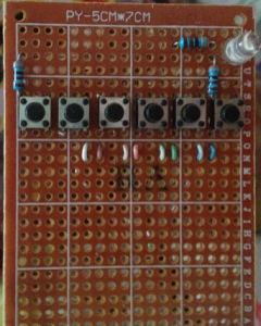
焊洞洞板,示意电路图如下:

dianlu


为了防止LED以及GPIO口电流太大,加了限流电阻。

board1

实际焊接图,请忽略左边五个按钮和左边的电阻,这是我留着备用的。

按照电路图连接到Pi上。

步骤2,安装python的gpio库,如果已经安装了,请跳过此步

cd /tmp
cd gpio
wget https://pypi.python.org/packages/source/R/RPi.GPIO/RPi.GPIO-0.5.7.tar.gz
tar xvzf RPi.GPIO-*.tar.gz
cd RPi.GPIO-*/
sudo python setup.py install
如果安装的时候出现错误:
source/py_gpio.c:23:20: fatal error: Python.h: No such file or directory
这是因为缺少Python.h文件,没安装python编译环境:
sudo apt-get install python-dev
步骤3:开始我们的python程序吧
#!/user/bin/env python

import RPi.GPIO as GPIO
import time
import urllib
import urllib2
import json

def mute():
url=’http://你的Pi的ip地址:8080/jsonrpc’
values = {“jsonrpc”:”2.0″,”method”:”Application.SetMute”,”id”:1,”params”:{“mute”:”toggle”}}

jdata = json.dumps(values)
req = urllib2.Request(url, jdata)
req.add_header(‘Content-Type’,’application/json’)
response = urllib2.urlopen(req)
return response.read()

GPIO.setmode(GPIO.BOARD)
GPIO.setup(11,GPIO.OUT)
GPIO.setup(12,GPIO.IN)
while True:
in_value= GPIO.input(12)
if in_value ==False:
mute();
GPIO.output(11,False)
time.sleep(0.5)
GPIO.output(11,True)
while in_value == False:
in_value = GPIO.input(12)

然后运行python key.py,按下按钮看看屏幕右上角已经有了静音标志了?再按一下,又消失了。
还可以在这个代码基础上修改做别的操作,希望这个能够起到抛砖引玉的作用。

Raspberry Pi 使用NFC模块读取标签

使用网上的教程,链接 http://www.geek-workshop.com/thread-10042-1-1.html 。

原文包含SPI和I2C总线两种方式,因为我不想插上一大把线,所以只用了I2C接口,所以内容有删节。

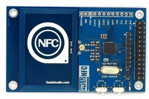
libnfc是首个遵循GNU(自由工程项目)通用公共许可证针对所有人都完全免费的低级别NFC软件开发包和编程应用程序接口。它提供了完整的透明度且免费供大家使用。该库目前支持调制ISO / IEC14443 A和B,FeliCa,Jewel/Topaz标签及数据交换协议(P2P)作为目标和启动程序。想了解更多关于libnfc的信息,可参考http://nfc-tools.org/ITEAD PN532 NFC模块配有双排引脚,可直接通过排线连接到树莓派,然后树莓派将驱动模块进行非接触式近场通信操作,如读写13.56M IC卡。

154149rr5dubo9wbj9wlrw

以下教程,演示如何在树莓派上使用libnfc通过SPI总线来驱动ITEAD PN532 模块。

1, 硬件链接

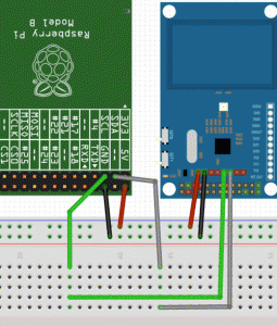
Itead PN532 Module是使用四条线连接,如下图

154152srjo5ttbbbza07bt

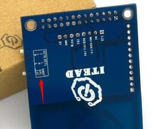
按照上图的连接方式,Itead PN532 模块是通过SPI总线与树莓派连接的,所以需要把NFC模块的工作模式设置为I2C模式,如下图:
即 :  SET0–>H   SET1–>L

154150t0vova0ahg3ta0u8

2,安装依赖的软件包
sudo apt-get update
sudo apt-get install libusb-dev libpcsclite-dev

3,下载并解压缩libnfc源码包
cd ~
wget http://dl.bintray.com/nfc-tools/sources/libnfc-1.7.1.tar.bz2
tar -xf libnfc-1.7.1.tar.bz2

4,编译与安装
cd libnfc-1.7.1
./configure –prefix=/usr –sysconfdir=/etc
make
sudo make install

5, 修改配置文件
cd /etc
sudo mkdir nfc
sudo nano /etc/nfc/libnfc.conf

将如下内容复制到/etc/nfc/libnfc.conf文件中:

# Allow device auto-detection (default: true)
# Note: if this auto-detection is disabled, user has to set manually a device
# configuration using file or environment variable
allow_autoscan = true

# Allow intrusive auto-detection (default: false)
# Warning: intrusive auto-detection can seriously disturb other devices
# This option is not recommended, user should prefer to add manually his device.
allow_intrusive_scan = false

# Set log level (default: error)
# Valid log levels are (in order of verbosity): 0 (none), 1 (error), 2 (info), 3 (debug)
# Note: if you compiled with –enable-debug option, the default log level is “debug”
log_level = 1

# Manually set default device (no default)
# To set a default device, you must set both name and connstring for your device
# Note: if autoscan is enabled, default device will be the first device available in device list.
device.name = “Itead_PN532_SPI”
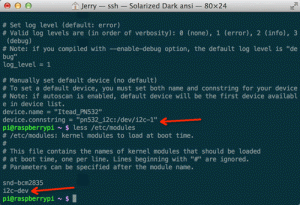
device.connstring = “pn532_i2c:/dev/i2c-1”

6,树莓派系统默认是将SPI模块的驱动关闭的,我们需要将其打开;

sudo nano /etc/modprobe.d/raspi-blacklist.conf

树莓派开启I2C总线,将/etc/modprobe.d/raspi-blacklist.conf中“blacklist i2c-bcm2708”变为“#blacklist i2c-bcm2708”
在/etc/modules末尾添加一行 “i2c-dev”

154152dpob3559dxp2xkp5

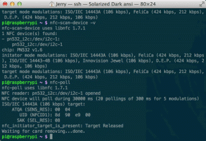
刷卡测试,运行效果如图:

154152sifdbr1fadiqz5ib

———————————————————————————————–
参考资料附录&相关链接:
A1. libnfc配置方法:http://nfc-tools.org/index.php?title=Libnfc:configuration
A2. libnfc安装教程:http://nfc-tools.org/index.php?title=Libnfc
A3. libnfc用户API:http://nfc-tools.org/index.php?title=Libnfc:API
A4. libnfc主页:http://nfc-tools.org/index.php?title=Main_Page
A5. libnfc学习例程:ibnfc:Examples” target=”_blank”>http://nfc-tools.org/index.php?title=Categoryibnfc:Examples
A6. Iteadstudio PN532 Module 网址 http://imall.iteadstudio.com/im130625002.html

A7. Disable R-Pi/RASPBIAN serial console for using UART0 http://learn.adafruit.com/adafruit-nfc-rfid-on-raspberry-pi/freeing-uart-on-the-pi
————————————————————————————————-
教程到此结束,谢谢大家!有问题请留言或微博@ITEAD创易工作室

以上为引用原文并修改了部分内容和顺序。当时测试时没有修改跳线,始终无法读到数据,后来查到PN532说明书,才知道要修改set0->H,set1->L(文中已添加),数据才读取成功。


规划:Pi读取NFC刷卡记录,然后传到网上,并通过微信、短信、微博通知。

场景:父母想知道孩子已经到达某处,可以通过这种方式获得通知。

后续文章会贴出后台部分。

Raspberry Pi 播放 1080p视频

看到网上说树莓派支持1080P视频的播放,专门下载了片子尝试,经常卡死。后来看到说超频后效果好一些。在xbian里面试验了一下,效果没有太大改善。

难道是硬盘原因?这个移动硬盘比较老,大概是5400转的。我通过网络尝试访问Pi,共享拷贝文件,居然只有20多k的速度,换了个比较新的硬盘,速度也没有改善多少,大概40多K,看样子不是硬盘的问题。

难道是usb hub的原因?这个hub比较老,难道是usb 1.0或者1.1的?在网上搜了一下,线材及usb hub本身原因,严重影响移动硬盘速度,甚至会损坏硬盘,所以不建议将硬盘接在hub上。将移动硬盘连直接接到Pi上,网络拷贝速度已经可以达到2.8M,虽然和电脑之间拷贝的20多M速度相比还很慢,已经算是可以接受了。用xbmc开始播放硬盘的1080P电影,果然不卡了,yeah!


总结,硬盘、摄像头之类的设备最好直接接在Pi上,鼠标键盘可以通过usb hub扩展,否则严重影响速度和效率。至于要不要超频,反而影响不是很大。

DO NOT use USB HUB to extend you movable disk or camera, it will slow down your read speed even you can not use it.

树莓派充当mp3播放器

最近想着通过Raspberry Pi来充当mp3用,因为没有显示器,只有音箱,所以就把音箱直接接在Pi的3.5mm耳机接口上。可以在电脑上或者手机上通过网页来播放音乐。也许有人问,有了电脑或手机为什么要这个,因为也许电脑、手机的外放效果不怎么样,接音箱总归好一些。而且对于我这个懒人,就喜欢躺床上,希望通过手机来控制一切,所以才诞生了这个想法。

基本步骤:

1.安装系统,本人使用的是xbian,理论上其他系统也可以。如果已经装好系统,可以跳过这一步

2.安装mpg123

命令: apt-get install mpg123

安装完毕mpg123,拷贝一个mp3文件到Pi中,可以运行mpg123 xxx.mp3(xxx.mp3为mp3文件名)看看能否正常运行。

本人在运行的时候出现找不到输出口的问题,大概是声卡驱动没有正确加载,运行以下命令解决:

sudo modprobe snd-bcm2835

3.安装lnmp,其实这里只需要安装nginx和php就可以了。

参照我之前的帖子 https://blog.wo.ai/archives/194 来进行安装

或者简单运行如下程序:

apt-get install nginx php5 php5-fpm php5-mysql php5-curl php5-gd php5-intl php-pear php5-imagick php5-imap php5-mcrypt php5-memcache php5-ming php5-ps
php5-pspell php5-recode php5-snmp php5-sqlite php5-tidy php5-xmlrpc php5-xsl

4.然后配置php sudo权限,这样php执行命令的时候不需要输入自己的密码

为 nginx,而想透过 PHP 发送irsend,用 root 输入指令 vi /etc/sudoers,
在档案最底加上以下一行:

www-data ALL=NOPASSWD: /usr/bin/mpg123

5.开始php旅程:

首先是index.php,用来遍历某个目录下所有的mp3文件,并显示出来:

//获取文件目录列表,该方法返回数组
function getDir($dir) {
$dirArray[]=NULL;
if (false != ($handle = opendir ( $dir ))) {
$i=0;
while ( false !== ($file = readdir ( $handle )) ) {
//去掉””.”、”..”以及带”.xxx”后缀的文件
if ($file != “.” && $file != “..”&&!strpos($file,”.”)) {
$dirArray[$i]=$file;
$i++;
}
}
//关闭句柄
closedir ( $handle );
}
return $dirArray;
}

//获取文件列表
function getFile($dir) {
$fileArray[]=NULL;
if (false != ($handle = opendir ( $dir ))) {
$i=0;
while ( false !== ($file = readdir ( $handle )) ) {
//去掉””.”、”..”以及带”.xxx”后缀的文件
if ($file != “.” && $file != “..”&&strpos($file,”.mp3″)) {
$fileArray[$i]=”/home/test/”.$file;
if($i==100){
break;
}
$i++;
}
}
//关闭句柄
closedir ( $handle );
}
return $fileArray;
}

读取mp3tag

function readmp3($mp3_file)
{
$fp=fopen($mp3_file,"rb"); //读取mp3文件
//首先判断是否有TAG,如果没有,那就没必要读取了,方法就是读取倒数128-126字节,看是否是TAG
//详情参看http://www.readlog.cn/archives/2961/
fseek($fp,-128,SEEK_END); //指针移到倒数128字节处
$tag=fread($fp,3); //读取倒数128-126字节位置的数据
if($tag=="TAG") //如果这3个字节是TAG,表明有TAG
{
$mp3=array();
//标题30个字节,从倒数125字节到倒数96字节
//现在直接读就可以了
$mp3['标题']=fread($fp,30);
//艺术家30个字节,从倒数95字节到66字节
$mp3['艺术家']=fread($fp,30);
//专辑30个字节,从倒数65字节到36字节
$mp3['专辑']=fread($fp,30);
//年份4个字节,从倒数35字节到32字节
$mp3['年份']=fread($fp,4);
//注释28个字节,从倒数31字节到4字节 (有的是30个字节,那就把倒数第2,3位归入注释了)
$mp3['注释']=fread($fp,28);
fseek($fp,1,SEEK_CUR); //跳过倒数第3位保留位
//第几首1个字节,倒数第2位
$mp3['编号']=ord(fread($fp,1));
//流派1个字节,就是倒数第一个字节了
//流派这里是存放的整型数据,可以写个函数来把数字变成具体的文字。
//具体含义参看http://www.readlog.cn/archives/2961/
$mp3['流派']=ord(fread($fp,1));
return $mp3;
}
}

生成mp3列表:

<?

//调用方法getDir(“./dir”)……可以是绝对路径也可以是相对路径
$filelist = getFile(“/home/test”);
//var_dump($filelist);
foreach($filelist as $file){
echo(“<li><input type=\”button\” onclick=\”checkMe(‘play.php?file=”.$file.”‘)\” value=\””.$file.”\”<br />”);
$mp3 = readmp3($file);
if($mp3){
echo($mp3[‘艺术家’].’-‘.$mp3[‘专辑’].’-‘.$mp3[‘标题’]);
}
}
?>
</ul>
<input type=”button” onclick=”checkMe(‘play.php?’)” value=”stop” />

页面基本完成了。

然后是play.php,根据传进来的文件名,通过后台播放:

<?php
$cmdline = “/usr/bin/sudo /usr/bin/killall mpg123 >/dev/null &”;
shell_exec($cmdline);
if($_GET[‘file’]){
$cmdline = “/usr/bin/sudo /usr/bin/mpg123 –loop -1 “.$_GET[‘file’].” >/dev/null &”;
echo($cmdline);
$output = shell_exec($cmdline);
echo($output);
}
?>

基本上大功告成了,这里的mp3文件名除了本地文件外,还可以是流媒体或者网址,都可以试试看。

英文中有个词是couch potato,我还是当bed potato吧。好好享受着音乐吧。


附:Raspberry Pi(树莓派)声音输出的设置

Raspberry Pi(树莓派)声音输出可以设置为自动,耳机输出,从HDMI输出三种,默认为自动

pi@aborn ~ $ sudo apt-get install alsa-utils
pi@aborn ~ $ sudo modprobe snd-bcm2835    #把声音模块加入内核
pi@aborn ~ $ sudo aplay /usr/share/sounds/alsa/Front_Center.wav
pi@aborn /opt/vc $ sudo amixer cset numid=3 2
numid=3,iface=MIXER,name=’PCM Playback Route’
; type=INTEGER,access=rw——,values=1,min=0,max=2,step=0
: values=2
pi@aborn /opt/vc $ sudo aplay /usr/share/sounds/alsa/Front_Center.wav
Playing WAVE ‘/usr/share/sounds/alsa/Front_Center.wav’ : Signed 16 bit Little Endian, Rate 48000 Hz, Mono
pi@aborn /opt/vc $ sudo amixer cset numid=3
numid=3,iface=MIXER,name=’PCM Playback Route’
; type=INTEGER,access=rw——,values=1,min=0,max=2,step=0
: values=0

pi@aborn /opt/vc $ sudo amixer cset numid=3 1
numid=3,iface=MIXER,name=’PCM Playback Route’
; type=INTEGER,access=rw——,values=1,min=0,max=2,step=0
: values=1

values取不同的值分别代表:
0=auto(自动), 1=headphones(耳机), 2=hdmi

在树莓派上使用RS232(连接到Psion5)

原文地址:http://blog.mrpjevans.com/2012/1 … ry-pi-to-a-psion-5/

(笔者注:Psion5是Psion公司出的一款掌上电脑)

树莓派的通用输入输出口(GPIO)由26针组成,是黑客们的最爱,能够使用模拟或者数字信号的操作。翻遍了手册,我发现居然连基本的串口都没有。也就是我们上个世纪的老朋友,RS232,这是一个低功耗版本。对于那些完全不知道我说什么的人,不用担心,即使这个帖子不太适合你。RS232看起来像是以前那些学校废弃的技术,但实际上它是我们身边最简单的两机通讯的方式。

庆幸的是,搞Pi的那些聪明的家伙,使用串口作为控制台,也就是说,你可以用它登录然后得到一个命令行。我白天的工作就是在一个数据中心管理一堆的服务器。尽管他们有很多最新的、功能强大的工具包,无一例外的是他们都配有串口。当显卡不能正常工作时,至少你还可以通过这个接口来登录系统。

Pi上提供的串口使用起来很简单。只需要4条线:电源,发送,接收,地。没有更简单的方法了,直接把这些线连接到电脑的COM口,对不对?

嗯,不对。这其中有一个问题,Pi用的电压是3.3v,RS232需要+12V作为高电平(1),-12v作为低电平(0)。Pi自身没办法做到,通过google可以找到很多现成的解决方案。幸运的是,有一个现成的芯片可以双向转换信号,让我们可以从pi的低电压信号转换成一个“真正的”RS232接口。这个价格大概是5镑,名字叫MAX3232CPE。只需要小部分的电容就可以。

到了我们开始干活的时候了。我从本地的Maplin买到了所有的配件(下面提供了链接和编号):
一个Max2323CPE集成电路(DT26D)
一个16针DIL IC插座(BL19V)(如果你有面包板,这个就不需要了)
5个0.1uF电容(N43CJ)
9针D-Type插座
线
杜邦线(A39GF)
一些洞洞板(FL17T)(虽然我强烈建议一开始用面包板)

当然还有:
一点焊接经验
一个COM/串口

我这里还出现了一个问题。作为Mac用户,我知道乔布斯多年前就放弃了RS232口,采用兼容性很好的usb接口。幸好Maplin还卖一个基于PL2303芯片usb转串口的适配器,在OS X上运行的很好,包括山狮,但是我花了不少时间来找驱动和步骤。

开始干活,这就是我们要做的:


最开始我在面包板上完成了,按照Joonas Pihlajamaa的步骤(链接在文末)。如果你还是个新手,在面包板上插IC芯片,还是要小心一些,把所有的针脚都插进去。在这个时候不需要用插座。下一步,我焊接了一个9针的连接器。我把RXD焊到针脚2,TXD焊到针脚3,地为针脚5(右上)。

现在你关闭Pi,从集成电路的1,6,8,10针脚连接这4条线到Pi。针脚1时左上,标记为P1。在它右边是针脚2。然后针脚1下是3,右边是4,以此类推。

这四条线是这么连接的:
Pin 1 – +3.3V
Pin 6 – Ground
Pin 8 – TXD (发送数据)
Pin 10 – RXD (接收数据)

将9芯的RS232连接到你的COM接口,然后打开Pi。
你的Pi应该正常启动,根本不知道建了新连接。现在把你的注意力放到你的电脑。

你需要有个软件能够连接到你的Pi。在windows上,你可以用PuTTY。在mac上,试试看MacWise,或者直接用linux上的命令行工具,比如screen

如果你打算用screen,来看看他是和么安装的

  1. $ screen -h

复制代码

命令不存在?那就安装吧

  1. $ apt-get install screen</p><p>$ screen /dev/ttyUSB0 115200

复制代码

或者你已经安装了MacPorts

  1. $ port install screen</p><p>$ screen /dev/tty.usbserial 115200

复制代码

注意:在/dev/可能有很多设备,取决于操作系统和驱动程序等。看看你的/dev/目录下是不是存在。可以找tty或者usb开头的那些。

屏幕应该会变成空白,按一次回车键后会出现登陆提示,然后可以到Pi的配置。

如果你用一个更高级的包,记住RS232工作前还需要配置。Pi的设置是115200bps(波特率),8位,无校验,一个停止符。这个通常标记为115200 8N1,你需要改成这个设置。一旦配置好,打开或者连接(取决于你软件怎么用)然后按回车就可以了。Pi的登录提示应该就会出来了。

无法运行?十之八九是你PC端的的RXD和TXD没接对。断开连接关闭Pi,在面包板上把这两条线换一下。如果这样还不工作,检查你终端的设置。

我决定通过给Pi届一个屏幕和键盘让它得到一个合乎逻辑的结论(在我的脑子里),也就是Psion5。然后一开始无法正常工作,因为不管是Psion还是Pi都希望自己是可以和电脑通信的“客户端”。我需要一个交叉线,把RXD和TXD交换一下,最后可以跑了。


只要在面包板上可以运行了,就很容易把IC移植到洞洞板,让它做一些持久地工作。

你可能奇怪为什么要这么做,事实是很多设备依旧在使用RS232通信。你可以在投影机、机顶盒甚至车上找到RS232接口。即使我一个很老的洗衣机上也有一个。所以,让Pi拥有一个很好用的RS232接口将会很有意思。通过google你还可以将目前登录命令行改成你想要的。我将会怎么用它?它将会是另外一个贴子。

Sources for this article:
Joonas Pihlajamaa
http://codeandlife.com/2012/07/01/raspberry-pi-serial-console-with-max3232cpe/

speakjava
https://blogs.oracle.com/speakjava/entry/serial_communications_with_a_raspberry

通过手机来控制家电

心血来潮想通过树莓派对家里的电器进行控制,网上查了不少资料,决定动手一试。首先决定对电暖器开刀,这个电脑有一个红外的遥控器,可以开关、定时、设定高低档功能,我要做的就是模拟遥控器对其发出指令。初级篇,通过电脑命令行进行控制,高级篇使用手机进行控制。

参照baoxiaozhong的红外接收http://www.shumeipai.net/thread-12265-1-1.html 设置好了红外接收器,然后尝试用相似的方法实现了红外发射器,成功控制电暖器,后续将考虑控制电视,空调等 设备。

初级篇:用电脑来控制电暖器

原理:

先通过红外接收模块,采集遥控器的指令,然后通过红外发射器模块模拟遥控器发送红外指令控制。

环境:xbian 1.0 alpha4

硬件:taobao上淘的10多块一个的红外接收模块及红外接收模块,此处不发地址,免得广告嫌疑。

连接方式:

红外接收器
vcc 连 pin1 (3.3v)
gnd 连 pin6(ground)
data连 pin12(gpio18)
红外发射器
vcc 连pin2(5v)
gnd连pin6(ground)
data连pin11(gpio17)

为什么这么连,我查了很久资料,后来在lirc_rpi原作者网站看到了,大概固定在程序里面了。
地址:http://aron.ws/projects/lirc_rpi/

步骤:
先通过红外接收器接收遥控器的编码,请参照http://www.shumeipai.net/thread-12265-1-1.html.
在用户目录生成了lircd.conf文件

我生成了KEY_UP,KEY_DOWN,KEY_0,KEY_1等分别代替开启、定时、低、高四个按钮

然后将它拷贝到/etc/lirc/remotes下,
sudo cp /home/xbian/lircd.conf /etc/lirc/remotes/xxx.conf (xxx随便你起名字,但是要和后面统一)
sudo vi xxx.conf
修改 name /home/xbian/lircd.conf 为 name xxx

sudo /etc/lirc/lircd.conf
增加一行

include “/etc/lirc/remotes/xxx.conf”

保存退出
现在可以测试了
sudo irsend SEND_ONCE xxx KEY_ON
sudo irsend SEND_ONCE xxx KEY_TIMER
sudo irsend SEND_ONCE xxx KEY_LOW
sudo irsend SEND_ONCE xxx KEY_HIGH

开始享受电暖器滴滴接收命令的的声音吧。

高级篇:通过手机来控制电暖器

安装LNMP
参照http://geekpi.cn/blog/2012/10/1908

apt-get install mysql-server mysql-client nginx php5 php5-fpm php5-mysql php5-curl php5-gd php5-intl php-pear php5-imagick php5-imap php5-mcrypt php5-memcache php5-ming php5-ps
php5-pspell php5-recode php5-snmp php5-sqlite php5-tidy php5-xmlrpc php5-xsl

mysql我没有做优化

配置nginx
先配置/etc/nginx/nginx.conf,需要做的就是限定线程数和开启gzip支持,gzip开启后将大幅降低传输html的流量占用。

worker_processes 1; #只有一个CPU,单进程即可

worker_connections 256; #一般支持100在线连接就达到raspberry pi的极限了

gzip on; #gzip开启取消前面的#让默认设置生效即可
gzip_disable “msie6”;

gzip_vary on;
gzip_proxied any;
gzip_comp_level 6;
gzip_buffers 16 8k;
gzip_http_version 1.1;
gzip_types text/plain text/css application/json application/x-javascript text/xml application/xml application/xml+rss text/javascript;

接下来设置/etc/nginx/sites-avaliable/default ,配置站点属性

root /var/www ; #站点存储位置

index index.php index.html index.htm; #加入index.php为默认页面

location ~ \.php$ {
fastcgi_split_path_info ^(.+\.php)(/.+)$;

fastcgi_pass unix:/var/run/php5-fpm.sock;
fastcgi_index index.php;
include fastcgi_params;
}

#开启php解析,使用php-fpm作为Fastcgi通信模块

然后配置php sudo权限,这样php执行命令的时候不需要输入自己的密码
为 nginx,而想透过 PHP 发送irsend,用 root 输入指令 vi /etc/sudoers,
在档案最底加上以下一行:

www-data ALL=NOPASSWD: /usr/local/bin/irsend

在/usr/share/nginx/www/下 编写cmd.php

<?php
$cmd = $_POST[‘cmd’];
if(!$cmd){
$cmd = $_GET[‘cmd’];
}
$device = $_POST[‘device’];
if(!$device){
$device = $_GET[‘device’];
}
if($cmd&$device){
$cmdline = “/usr/bin/sudo /usr/local/bin/irsend SEND_ONCE “.$device.” “.$cmd ;
echo($cmdline);
$output = shell_exec($cmdline);
echo($output);
}
?>

然后就可以通过http://ip地址/cmd.php?cmd=KEY_UP&device=xxx控制你的设备了。
这里的xxx是可以不同设备的哦。看你前面irrecord里面配置的

当然这种方式操作不方便,和shell操作差不多,所以可以自己做一个html页面,放上若干按钮,每个按钮分别调用cmd.php上面的指令。

这是个简单的例子

<html xmlns=”http://www.w3.org/1999/xhtml”>
<head>
<meta http-equiv=”Content-Type” content=”text/html; charset=utf-8″ />
<meta name=”apple-mobile-web-app-capable” content=”yes”>
<title>智能家庭控制台</title>
<script type=”text/javascript” src=”js/jquary-1.7.1.js”></script>
<script type=”text/javascript”>
var xmlHttp;
//创建XMLHttpRequest对象
function createXMLHttpRequest(){
if (window.ActiveXObject){
xmlHttp=new ActiveXObject(“Microsoft.XMLHTTP”);
}else if (window.XMLHttpRequest){
xmlHttp=new XMLHttpRequest();
}
}
function checkMe(url){
createXMLHttpRequest();
xmlHttp.open(“post”,url,true);
xmlHttp.onreadystatechange=send; //用send函数进行发数
xmlHttp.setRequestHeader(“Content-Type”,”application/x-www-form-urlencoded;”);
xmlHttp.send(null);
}
function send(){
//alert(“指令成功发送!”);
}
</script>
</head>

<body>

<div id=”content”>
<div id=”menu_mode”>
<ul>
<li><input type=”button” onclick=”checkMe(‘cmd.php?cmd=KEY_ON&device=heater’)” value=”开/关”/></li>
<li><input type=”button” onclick=”checkMe(‘cmd.php?cmd=KEY_LOW&device=heater’)” value=”低档”/></li>
<li><input type=”button” onclick=”checkMe(‘cmd.php?cmd=KEY_HIGH&device=heater’)” value=”高档”/></li>
<li><input type=”button” onclick=”checkMe(‘cmd.php?cmd=KEY_HIGH&device=heater’)” value=”定时”/></li>
</ul>
</div>
</div>
</body>
</html>

然后通过http://ip地址/index.html访问

对于使用iphone或者ipad的用户,还可以把网页快捷方式放到主屏幕,打开就是一个操作界面,是不是很来福啊?

安装Siri Proxy

本文为本站首发,树莓派论坛转载,如果需要转载请注明作者及出处。

原文地址:

How to Install Siri Proxy Tutorial [Video]

安装之前,需要下面几个先决条件:
1.最好安装一个ubuntu.可以实际安装一台机器,也可以装在虚拟机上
2.只能安装在4s上,我未测试其他设备,可能不能工作,而且不合法
3.只有连上wifi的时候才可用,并且iphone和siri proxy在一个局域网内。虽然可以通过vpn远程,但是我尽量保持简单和直接
4.本文只覆盖初始化安装,以后我告诉你们如何增加一些插件来增加体验
5.任何人都可以做到,包括你,不要害怕
6.最后,感谢Pete创建了SiriProxy,并提供基础

如何安装:
预备步骤:
1.如果已经有了ubuntu,直接下一步。没有的话,可以在windows或者mac上装一个,mac上可以装Parallels或者vmware fusion运行ubuntu虚拟机,我用的是parallels
2.安装ubuntu的最新更新,参看视频1:00时刻(视频需要翻墙)
3.如果你用paralles或者其他虚拟机,需要设置虚拟机实通过bridge模式,这样可以联上互联网,参看视频4:00
4.设置dropbox,这是个可选步骤,我觉得这样方便一些。你需要有地方传输你iphone上生成的证书,你可以用邮箱,我用的是dropbox

命令行步骤:

这些步骤都可以参考视频,每个都有时间戳作为参考。简单的在终端复制粘贴这些命令,然后按照指令执行。

命令1:时间:5:44(此处安装必要的库)
sudo apt-get install dnsmasq ruby build-essential openssl libreadline6 libreadline6-dev curl git-core zlib1g zlib1g-dev libssl-dev libyaml-dev libsqlite3-0 libsqlite3-dev sqlite3 libxml2-dev libxslt-dev autoconf libc6-dev ncurses-dev automake libtool bison subversion
选择y继续,

命令2:时间6:13
sudo nano /etc/dnsmasq.conf
找到62行: #address=/double-click.net/127.0.0.1
在他下面增加:address=/guzzoni.apple.com/(你机器的ip地址)
按ctrl+o,回车保存,按ctrl+x退出

命令03: Time 7:42
sudo /etc/init.d/dnsmasq restart

命令 04: Time 7:55
bash < <(curl -s https://raw.github.com/wayneeseguin/rvm/master/binscripts/rvm-installer)
命令 05: Time 8:20
[[ -s “$HOME/.rvm/scripts/rvm” ]] && . “$HOME/.rvm/scripts/rvm”
命令 06: Time 8:33
echo ‘[[ -s “$HOME/.rvm/scripts/rvm” ]] && . “$HOME/.rvm/scripts/rvm” # Load RVM function’ >> ~/.bash_profile
命令 07: Time 8:47
rvm install 1.9.3

这条命令需要执行一段时间,尤其编译阶段

命令 08: Time 9:22
rvm use 1.9.3 –default
命令 09: Time 9:32
git clone git://github.com/plamoni/SiriProxy.git
命令 10: Time 9:49
cd SiriProxy
选择y继续(我感觉不对,没有去验证)

命令 11: Time 10:06
rake install
命令 12: Time 10:21
mkdir ~/.siriproxy
命令 13: Time 10:31
cp ./config.example.yml ~/.siriproxy/config.yml
命令 14: Time 10:43
siriproxy gencerts
命令 15: Time 11:04
siriproxy bundle
命令 16: Time 11:23
rvmsudo siriproxy server
这条命令启动Siri Proxy,成功的话,会提示”Starting SiriProxy on port 443..”

在iphone 4s上设置

1.首先你要取得我们在上面第14步生成的证书,在4s上安装。你可以使用dropbox或者邮件传输到iphone,看视频的11:40
这个证书在 ~/.siriproxy/ca.pem,你需要查看隐藏文件,一旦证书到你的iphone,选择安装,参照视频12:44

2.进入iphone wifi设置,选择wifi连接左边蓝色简单按钮,记住,你的手机需要和你的siriproxy在一个局域网。在dns那里,把dns修改为siriproxy的ip地址,参看视频12:59

3.测试siri,按住home键,说“test siri proxy”,siri会回复你,“siri proxy is up and running”,在你的终端上面会显示你的语音包。

虽然看起来很复杂,你大概需要不到一个小时。

用Siri来控制车库门[翻译]

本文为本站首发,在树莓派论坛转载,其他网站转载需要指明出处及作者信息。

原文:
https://www.raspberrypi.org/forums/viewtopic.php?f=63&t=25118&hilit=siriproxy&sid=aa0660b88dd63482d287d7fb089e0d60

hi,这是我第一个树莓派的项目,SiriProxy。它运行在树莓派上,使用wiringPi访问派的GPIO口,并发一个延时的on/off信号。这个延时信号用来控制我车库门。所以我可以在iphone上用siri来控制我的车库门。

可能有其它的方式来做同样的事情,比如在Pi上跑一个web服务器来访问Pi的GPIO端口,但是我只是简单的做了一个,符合我自己的需求,并且运行的一切正常。

我的派在整个安装过程中都用root用户运行,这样可以比较简单一些(原文粗制滥造)。我用wheezy版本。

下面这个链接 http://www.idownloadblog.com/201 … oxy-tutorial-video/ 告诉你怎么安装和运行siriproxy。如果你按照这些步骤,并且把11,12,13步的顺序更换为12,13,11。顺便说一下,命令7大概需要在PI上编译90分钟。

然后开始安装wiringPi,可以从 https://projects.drogon.net/rasp … wnload-and-install/ 获得。

一旦这些都安装好了,我们只需要更改一下siriproy里面自带的ruby脚本的例子。
编辑/root/SiriProxy/plugins/siriproxy-example/lib/siriproxy-example.rb 文件

找到这几行:

listen_for /test siri proxy/i do
say “Siriproxy is up and running!” #say something to the user!

request_completed #always complete your request! Otherwise the phone will “spin” at the user!
end

在它后面追加这几行

listen_for /open the garage door/i do
say “Opening the garage door..”
request_completed
system(“gpio mode 1 out”)
system(“gpio write 1 1”)
system(“sleep 0.5”)
system(“gpio write 1 0”)
end

listen_for /close the garage door/i do
say “Closing the garage door..”
request_completed
system(“gpio mode 1 out”)
system(“gpio write 1 1”)
system(“sleep 0.5”)
system(“gpio write 1 0”)
end

你可以看到,ruby脚本简单的用system命令来访问wiringPi,设置GPIO针脚作为输出端口,设置它半秒高电平,半秒低电平。

你可以让siri调用任何你在命令行终端能用的命令,比如说通过无密码的SSH登录到远程的电脑让它关机或重起。

listen_for /turn off my laptop/i do
response = ask “Are you sure you want me to shut down your laptop?”

if(response =~ /yes/i)
say “OK, I’ll shut it down now..”
system(“ssh root@192.168.1.74 shutdown -h now”)
else
say “OK, I wont!”
end

request_completed
end

你可以把树莓派放在不同房间使用不同的命令控制,但只使用一个siriproxy服务器。注意:每次你修改完配置后,你需要在重起服务器之前运行”siriproxy bundle”命令。

这里还有一个我安装过程的演示视频。

http://youtu.be/NUJ5z76Xv5o

墙内的朋友安了吧,墙了。